Monday, December 31, 2007

Engine Reassembly Part II

There was still a lot of residue from material blasting the head, so I needed to clean it well with spray carb cleaner, and compressed air. I have no air compressor, so I stole an idea from instructables.com to make a simple air blower from an empty spray can, the presta valve from a bicycle tube, and JB Weld. Redneck Air cans are GOOOOO!


Cam chain tensioner install is pretty mean with the need to preload the spring all the way "open" so that it does not interfere with the cam/sprocket/chain reassembly. I rednecked a tool to hold it open out of wire:


The string (floss) helps guard against it falling into the bowels of the motor

One last check before saying goodbye to the head


All closed up!


Saturday, October 13, 2007

Engine Reassembly Part I

XRs Only rebuilt the top end, taking the cylinder sleeve to two sizes over-bore, and freshening up the head with a 3 angle valve grind, port/polish, new stainless valves with narrowed stems, and a 10.5:1 J&E Piston. They also recommended replacing the timing chain, so that will happen as well. Bueno.

Bead blasted gorgeousness thanks to Meyer's Sandblasting in Fruitvale anex of Oakland.


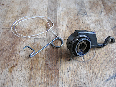
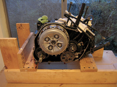
Time to install a new timing chain. Off with the clutch...Inner clutch assy. lock nut is really on there. Need cheeterbar on the socket handle, and to track down a spanner wrench for the grabber. ugh. soft aluminum.


Someone on a moto forum suggested welding the old steel clutch plates together and then a handle to them. Makes much sense, especially since the ones I got are kind of old and warped:

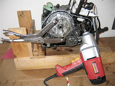
I opted for the Impact Wrench solution. Craftsman model 27299, rated at 250ft/lbs. Bap!Bap!Bap!Bap!Bap!Bap!Bap!Bap!Bap!Bap!Bap!Bap!Bap!Bap!Bap!Bap! and it was off like nothing!

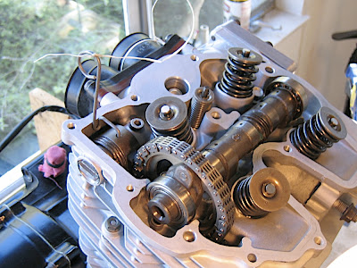
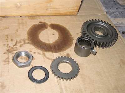
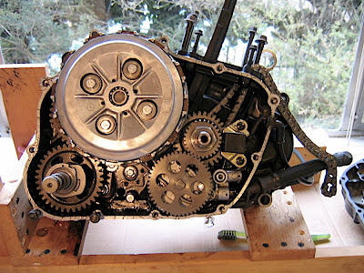
Same deal for the lock nut that holds everything down for the main drive shaft. Notice that the splines are keyed so that they only go on a certain way. This ensures that the pulse generator (that detached black box thing to the right of the drive shaft) gets impulse from the pulse rotor nubbin at the right time.


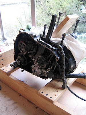
OK, new timing chain looped onto the shaft and ready to go. Funny, the one it replaced did not seem to have stretched in comparison! Nothing like waisting a lot of time and $ strictly for experience alone!


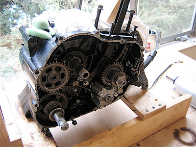
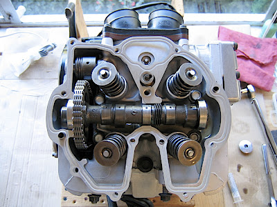
Everything ready for closing up now. One final look before gasket and gasket sealer goop. Opted for the soft cure kind, but in retrospect would have just not used it; nothing wrong with a little oil leaking out there compared to the mess of trying to take that clutch cover off next time around. real men don't use gaskets.


My accomplice chad torquing down the case nuts.

Stator reassembly was pretty uneventful (no gasket goop this time). So here's the whole bottom end, ready to go:


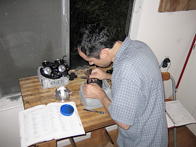
Here, we've got an action shot of gapping the piston rings. Very exciting.


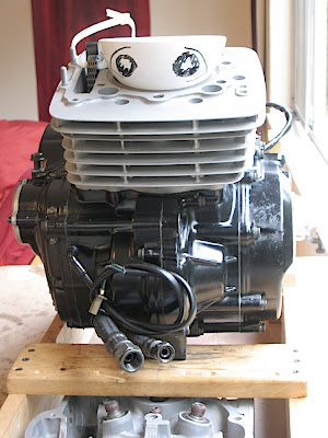
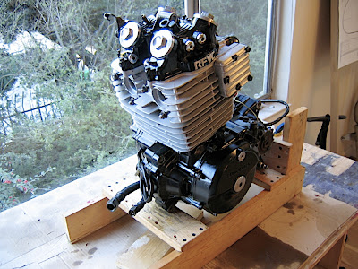
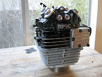
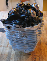
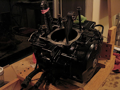
A whole bunch of fussing and worrying later and the jug's onto the bottom end, with 10.5:1 high comp. piston!

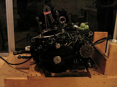
Here's where it sits for now until the head is cleaned up enough for reassembly.

Saturday, September 22, 2007

fuel tank prototype

Prototype using the LOST FOAM method, where you do a layup around polystyrene foam, and then pour in some acetone to melt the foam away. I encased the foam in packing tape with PVA coating so that the interior lining of the tank is not too ugly. Not sure about this technique, because it leaves a surface that'll need a lot of fairing.


Thursday, July 5, 2007

airbox fab.

Originally, I had thought to just attach a couple pod filters to the carb, but there's not enough room with the monoshock there. Plus I've read that pod filters can make it a real pain to get the jetting correct. Also, with no aft attachment place, the carbs are more prone to wiggling. So I decided to use the existing air boots on the inlet side and attach them to an airbox of my own design.

The original airbox was rotted out from neglect and had all sorts of ugly bits that would normally be obscured by side panels. So here's an attempt to make a cleaner airbox with a bit more filter surface area for sucking.

Construction approach was to do a final layup around a male mold and cut around the circumference to lift the halves off. Using this technique allowed me to do a small layup around this circumference beforehand, so that I had a good mold to make a joint piece from.

Anyway, here's the foam plug getting shaped:


The plug waxed and ready for the layup:


Here is the joint piece assembly:


Layup done, vacuum bagged to minimize voids:


Outer surface need a bit of fairing once the resin cured:

I marked the circumferential cut with masking tape and took my DREMEL OF FEAR to it:

BAM!!!

Fitting the two halves together with the joint interior, then epoxying the joint to the forward side


I fabbed up a little backfire screen that the air filter will rest against. This is still twice the surface area than the stocker. Ought to be good enough for the time being


I then made a spring loaded "cage" that will be used to press against the foam filter element along the edges to form a reasonably tight seal along the backfire screen edges.

Here's where it sits now; hope it fits!